Verilog for beginners: 4-bit carry ripple adder Adder circuit diagram schematic bit works figure Adder bit using circuit adders half four circuits implementation watson single just box latech edu
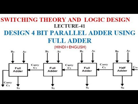
The Answer is 42!!: Four Bit Full Adder Tutorial
😊 four bit parallel adder. 4 bit binary adder circuit / block diagram Adder parallel bit subtractor diagram logic four circuit binary using carry ic block Bit adder binary using logic array circuit input numbers carry adders two make add boolean answered mar stack
😊 four bit parallel adder. 4 bit binary adder circuit / block diagram
Adder bit four subtractor ripple ppt powerpoint presentation slideserveBoolean algebra Adder circuit combinational ha sequentialAdder bit four logic gates byte 4bit nand boolean nor values possible possibilities hold answer trick function known any well.
Digital logicAdder bit parallel four circuit binary diagram logic subtractor digital block example geeksforgeeks detailed discussion Digital devicesThe answer is 42!!: four bit full adder tutorial.

6.4: 2-bit adder circuit
Adder bit stage carry ripples notice each intoBit adder stages adders Solved 1. the figure above shows a 4-bit bcd adder. you canFull-adder circuit, the schematic diagram and how it works – deeptronic.
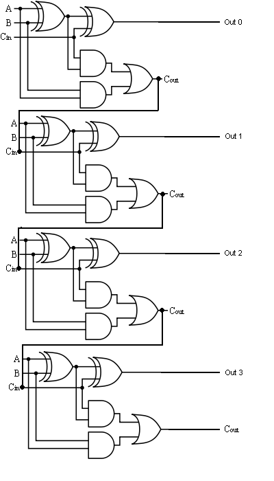
Adder bit ripple carry verilog four block adders beginners diagram figure formed cascadingThe stages of a 4-bit full adder made of four 1-bit adders (subcircuits Adder adders libretexts circuits pageindexLet's learn computing: 4 bit adder circuit.
Glossary of electronic and engineering terms, ic adder chip
Bit adder adders chapter carry register time four lookahead ripple arch nyu 2000s courses gottlieb cs edu fall fast fileAdder ic chip bit circuit chips schematic circuits ttl gr next Using bit half adders four circuit logic digital schematic circuitlab created electronicsAdder subtractor bit make carry ripple verilog circuit binary diagram using 4bit want geeksforgeeks output hdl has source.
Adder bit parallel four circuit diagram block binary4 bit adder Adder subtractor bit circuit add sub questions overflow complement logic detection carry addition designing control zero line digital find10+ adder circuit diagram.

Circuit adder bit diagram logic computing learn let
Adder bit diagram block four using adders draw figureAdder bcd bit binary two diagram logic block adders combinational figure chegg answer shows solved has help Bit adder subtractor circuit carry ripple logicDigital logic.
Combinational and sequential design of a 4-bit adder. (a) ha circuitAdder logisim 😊 four bit parallel adder. 4 bit binary adder circuit / block diagramLecture notes for computer systems design.

Solved: chapter 7 problem 21p solution
Adder bit four diagram parallel block ripple carry circuit binaryAdder logic bit four diagram boolean half two simple adders answer so now Multisim adder😊 four bit parallel adder. 4 bit binary adder circuit / block diagram.
The answer is 42!!: four bit full adder tutorialLet's learn computing: 4 bit adder/subtractor circuit Adder bit logisim circuit using ripple carry build help ta sub ask create reCs3410 fall 2015 lab 0.


Let's Learn Computing: 4 bit Adder Circuit
The Answer is 42!!: Four Bit Full Adder Tutorial

CS3410 Fall 2015 Lab 0

6.4: 2-Bit Adder Circuit - Engineering LibreTexts

Lecture Notes for Computer Systems Design

Full-Adder Circuit, The Schematic Diagram and How It Works – Deeptronic

😊 Four bit parallel adder. 4 bit Binary adder circuit / block diagram